An orthopantomogram (OPG) is a tomographic radiograph that uses a focal trough approximating the curve of the mandible to provide a view of the teeth and facial skeleton. This article provides a guide to identifying key anatomical features on the radiograph and outlines its use in identifying pathology such as dental disease, cysts and traumatic injuries An orthopantomogram to the hard tissues of the face.
An OPG is often ordered by dentists as a screening tool as it gives a complete view of the teeth and jaws. The dosage of radiation received by the patient is approximately 0.014 mSv, which is less than that of a standard chest X-ray at 0.02 mSv.1 Being an extra-oral radiograph, there is less limitation in taking the image when the patient has difficulty opening their mouth or where a prominent gag reflex prevents intra-oral films being used.
During exposure of the patient, the head of the X-ray generator and the detection unit circles the head of the patient. This movement focuses the image of the teeth and mandible but can result in artifact due to patient movement. The mandible is recorded in a protrusive position because of the use of a ‘bite block’ to position the patient in the correct focal trough. This will result in the condylar head of the mandible being located anterior to its rest position in the glenoid fossa. The cervical spine may obscure the anterior structures of the dentition because of superimposition, and the occipital bone may project over the rami of the mandible of the opposite side.
Hard and soft tissue identification
Systematic review of the OPG can simplify analysis of what may first appear to be a complicated image. One method would be:
- Count all teeth present and their positions, noting missing or misplaced teeth.
- Follow the contours of the mandible from right (left side of the image) to left, noting condylar head size/shape, continuity of external border of the ramus and body, and uniformity of the internal density of the bone. Also note the path of the inferior alveolar neurovascular canal ending in the mental foramina.
- Identify the maxillary sinuses and note any opacities or lucencies that may be present. Follow the cortical outlines for continuity.
- Check peripheries of the image for cervical spine, zygomatic, submandibular or hyoid abnormalities.
In addition to the dentition that can be seen, other hard tissues identifiable can include those shown in Figure 1. Soft tissue structures that can be identified because of their density are shown in Figure 2.
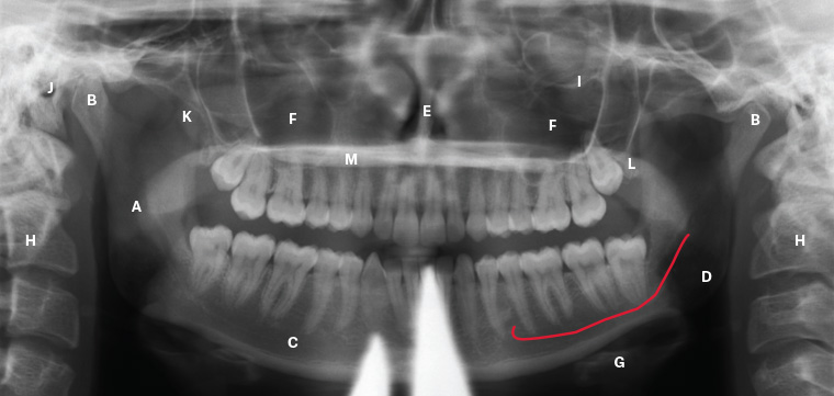
Figure 1. Key anatomical hard tissues; to be noted on this orthopantomogram is the use of a lead apron during exposure, producing the anterior artifact
A. Ramus of the mandible; B. Condylar head of the mandible; C. Body of the mandible; D. Canal of the inferior alveolar neurovascular bundle (shown in red); E. Nasal septum; F. Maxillary sinuses; G. Hyoid bone; H. Cervical spine; I. Inferior orbital rim; J. External auditory meatus; K. Coronoid process of the mandible; L. Tuberosity of the maxilla; M. Hard palate (horizontal radiolucency)
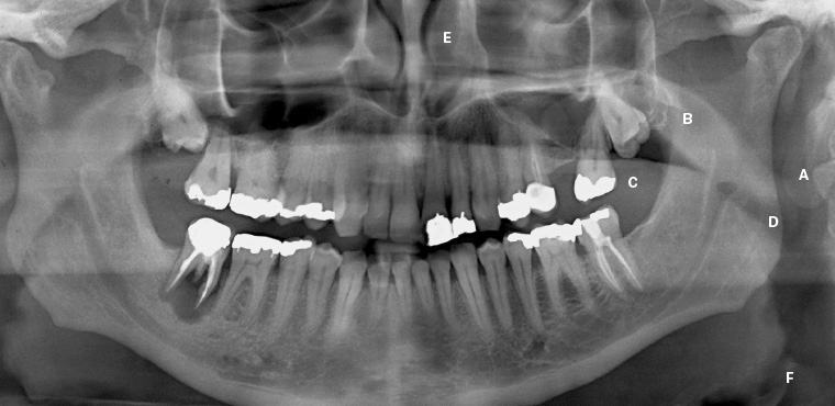
Figure 2. Soft tissue structures often seen on an orthopantomogram. Note the air space created by the tongue can be minimised during exposure by having the patient force their tongue onto the roof of the mouth. The posterior air space will commonly vary on either side as the patient may swallow or move their tongue during the exposure.
A. Pina of ear; B. Soft palate; C. Dorsum of tongue (note air space between tongue and palate); D. Oropharyngeal air space; E. Inferior nasal turbinate; F. Epiglottis
Teeth are readily identified on an OPG. Intra-oral radiographs give finer detail of tooth structure, but the OPG is a useful tool for screening. Figures 3 and 4 illustrate normal structures associated with the dentition.
Figure 3 is an OPG showing the full complement of 32 adult teeth. Identification of the teeth is by quadrant and tooth number. Quadrant is stated first, and then tooth number, as shown in Figure 5. Note that in Figure 3, teeth 15 and 12 have undergone root canal treatment, as have teeth 26 and 36.
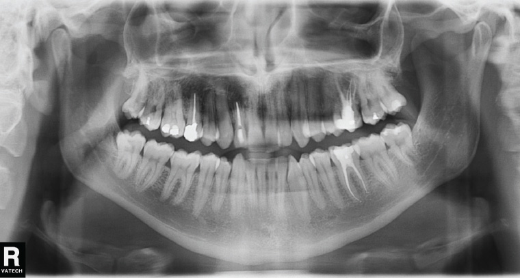
Figure 3. Adult orthopantomogram
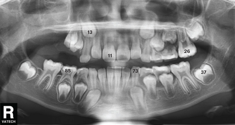
Figure 4. Orthopantomogram showing tooth numbering of both permanent and deciduous teeth
Deciduous (baby) teeth are labelled 1–5 in quadrants 5–8 as a continuation of the method shown in Figure 5, or occasionally labelled A–E (Figure 6).
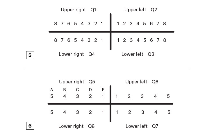
Figure 5. Identification of adult teeth by quadrant (Q) and tooth number
Figure 6. Identification of deciduous teeth by quadrant (Q) and tooth number
Pathology: Odontogenic disease
Tooth decay is the demineralisation of enamel and dentine due to organic acid production by oral bacteria. This demineralisation can be seen on the OPG within the tooth structure. When the pulp, or ‘nerve’, of the tooth is infected, it will often become necrotic, leading to an abscess in the underlying bone. This can be shown as a radiolucency under the affected roots (Figures 7–9).

Figure 7. Left segment of an orthopantomogram showing decay in the lower left third molar (38) and the distal of the lower left second molar (37)
Figure 8. Right segment of an orthopantomogram of teeth with dental work in place
A. Metallic restoration; B. Tooth-coloured restoration; C. Decay; D. Abscess
Figure 9. Right segment of an orthopantomogram showing odontogenic bone pathology
A. Root canal treated tooth; B. Large dental abscess
Impactions of the third molars are a common indication for ordering an OPG, and these impactions are classified according the angle of impaction of the teeth (Figure 10).
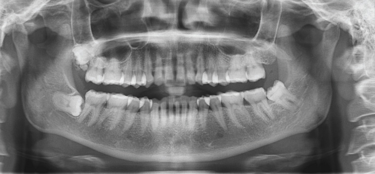
Figure 10. Adult orthopantomogram showing impacted third molars: horizontal impaction of the right lower third molar (48) and a mesio-angular impaction of the lower left third molar (38). The shadowing of the roots of the 38 is due to the superimposition of the inferior alveolar neurovascular canal. A ‘supernumary’ tooth can be seen preventing its eruption. The upper left third molar (28) is missing.
Atrophy of the mandible and maxilla can occur once teeth are removed (Figure 11). This is due to loss of alveolar bone, which is present to support teeth, and subsequent ongoing loss of basal bone. When severe, as in Figure 11, pathological fracture of the mandible can occur (Figure 12), as well as neurosensory changes to the inferior alveolar nerve due to loss of overlying bone.
Radiolucent lesions may be identified in either the maxilla or mandible. These may be cysts associated with teeth (dental in origin or odontogenic) or infective, developmental or other less common pathological causes such as metastases or metabolic conditions. Cystic lesions have well-defined borders and are often asymptomatic. They may or may not be in contact with the teeth, whereas a dental abscess is usually painful and always in contact with the associated tooth. All odontogenic cysts are benign but require removal to prevent bone destruction and infection. Locally aggressive benign neoplastic lesions such as odontogenic keratocystic tumours (OKCTs) and ameloblastomas can only be differentiated from other lesions via biopsy of the linings/contents. A referral is required for biopsy.
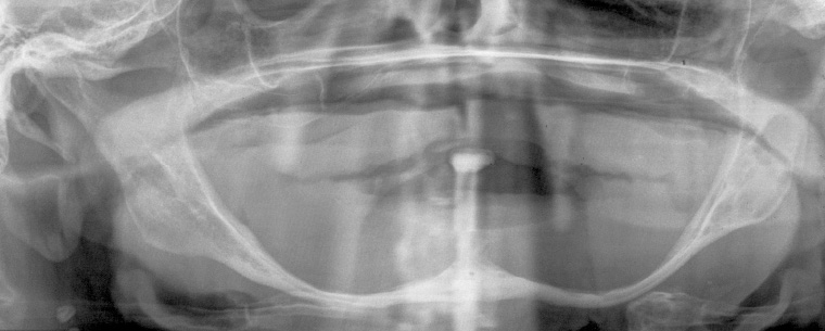
Figure 11. Orthopantomogram of an adult edentulous patient
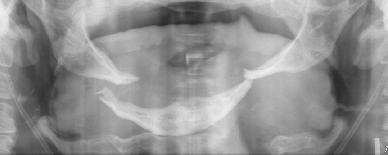
Figure 12. Orthopantomogram of an edentulous fractured mandible, showing bilateral ‘bucket handle’ fracture of the atrophic mandible. Treatment is difficult because of low bone stock at fracture sites.
Figure 13 is an example of an impacted lower right third molar (48) with an associated dentigerous cyst. In this case, the cyst has resulted in inferior displacement of the third molar. An OKCT may also give this appearance, but it can only be differentiated by histological analysis of the cyst lining. OKCTs have a recurrence rate of up to 62%2 and require ongoing radiographic follow-up for life.
Figure 14 shows a large maxillary cystic lesion with internal calcification associated with an impacted upper right molar in a patient of mixed-dentition stage. Enucleation confirmed a complex odontoma.
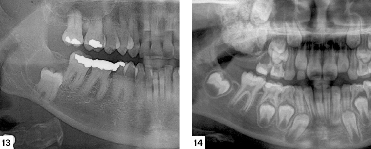
Figure 13. Right segment of an orthopantomogram illustrating a cyst associated with the impacted right lower third molar (48)
Figure 14. Right segment of an orthopantomogram illustrating a radio-opaque maxillary lesion
Trauma
Patients with facial trauma will usually present to the emergency department for assessment. In some cases, such as undisplaced fractures or distracting injuries, the patient may present to their general practitioner for assessment after discharge from the hospital. Where trauma history suggests a fracture may be present, an OPG can be useful, especially where the mandible is involved. Fractures of the facial bones may be seen on the OPG, but overlap and angulation commonly require further views via either plain radiographs or computed tomography.
Assessment of the OPG is done via the standard screening method with particular emphasis on cortical continuity of the mandible. The most common site of fracture is the angle (32%), with a second fracture at the parasymphysis seen in 40% of patients.3
Fractures of the mandible can clearly be seen on most OPGs; however, in some cases, cortical overlap may necessitate a second perpendicular view. In these cases, a posteroanterior view can be ordered (refer to Figures 15 and 16).
Traumatic dislocations may occur and sometimes require sedation/anaesthesia for reduction. Although traumatic dislocations can be diagnosed clinically, the OPG can illustrate the condition clearly. Note in Figure 17 that both condylar heads are anterior to the articular eminences, preventing them from moving distally into the glenoid fossae.
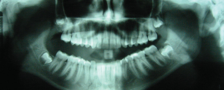
Figure 15. Orthopantomogram showing bilateral fracture of the mandible seen at the left angle and right parasymphysis
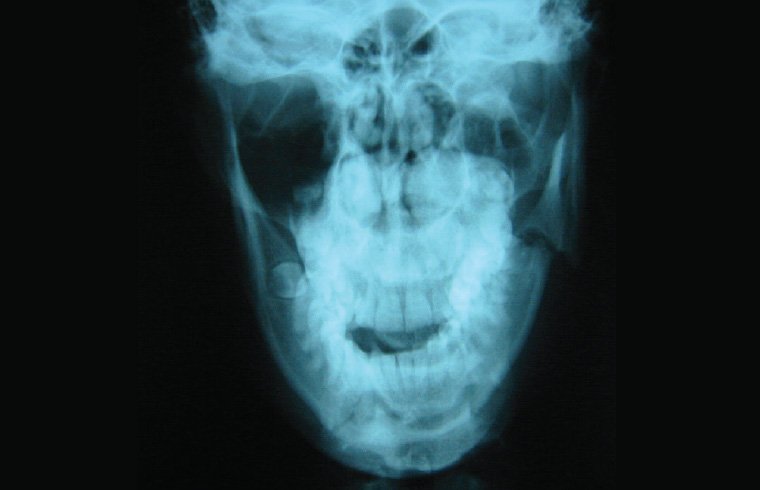
Figure 16. Alternative orthopantomogram view of patient in Figure 15; overlap of the segments of the left angle can often be seen more clearly on a plain posteroanterior view
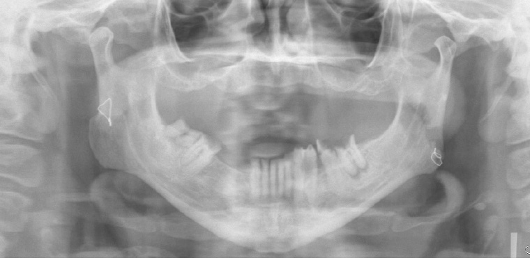
Figure 17. Orthopantomogram showing bilateral mandibular dislocations
Conclusion
The OPG provides a useful screening radiograph for examination of the dentition and facial skeleton. It is commonly ordered by dental practitioners to assess the position of the third molars and obtain a baseline identification of new patients. It is valuable to give an overview of the patient’s dental condition and to investigate possible pathology of the teeth and their supporting bony structures. It can also be used to identify traumatic injuries, particularly to the mandible.
The use of a systematic approach to viewing the radiograph should be used, and an understanding of the anatomy of the area is needed to fully assess the image.
Resource
- State Australian Dental Association – Continuing Professional Development courses in OPG interpretation